Cart is empty
- Description
- Akyapak has 54th years of experience and engineering expertise in a variety of products. Akyapak’s passion and dedication, which are reflected in every Akyapak machine in the market, to provide premium engineered solutions allow us to be more than your typical machinery manufacturer.
- FRAMES: The base frame of the machine consists of robust steel profiles and frames of motion axes consist of cast iron. The frame of the machine is designed with FEM simulation and thus mechanical solidity is guaranteed, optimizing suitable material selection, vibration and tension damping, and dimensional stability.
- SUPERIOR INDEPENDENT SPINDLE MOTION ABILITY IN 3 AXIS: The 3 ADM is equipped with sub-axis (z-axis) that enables independent control of spindles along 500 mm in the length of beam without repositioning it. After making a hole in the beam, there is no need to drive the beam to make another hole in the z-axis. Each spindle can move independently in 3 axes while the beam is stationary. This feature reduces processing time considerably and increases efficiency (approx. 3 times faster than the 2 ADM model).
- The independent motion ability provides combining operations: While processing one side of the flange, it is possible to perform other operations (drilling, marking, tapping, milling, etc.) independently on the opposing flange and web.
- ABILITIES: Drilling, milling, tapping, countersinking, layout marking, beam, channel, tube, angle, plate
- SPINDLE MOTORS: The 3 ADM is equipped with servo motors that provide precise motion and includes 3 high speed 22 kW spindle motors
- MOVEMENTS: The roller linear guidance system, which provides high rigidity and a load carrying capacity, is used in all internal axis of the frame. This system supports all loads and moments from all directions
- Accurate positioning and high feed rates are guaranteed with servo motor driven ball screws
- FOR MORE INFORMATION SEE PRODUCT FEATURES TAB
- Manufacturer
- Product Features
- Akyapak has 54th years of experience and engineering expertise in a variety of products. Akyapak’s passion and dedication, which are reflected in every Akyapak machine in the market, to provide premium engineered solutions allow us to be more than your typical machinery manufacturer.
- FRAMES: The base frame of the machine consists of robust steel profiles and frames of motion axes consist of cast iron. The frame of the machine is designed with FEM simulation and thus mechanical solidity is guaranteed, optimizing suitable material selection, vibration and tension damping, and dimensional stability.
- SUPERIOR INDEPENDENT SPINDLE MOTION ABILITY IN 3 AXIS: The 3 ADM is equipped with sub-axis (z-axis) that enables independent control of spindles along 500 mm in the length of beam without repositioning it. After making a hole in the beam, there is no need to drive the beam to make another hole in the z-axis. Each spindle can move independently in 3 axes while the beam is stationary. This feature reduces processing time considerably and increases efficiency (approx. 3 times faster than the 2 ADM model).
- The independent motion ability provides combining operations: While processing one side of the flange, it is possible to perform other operations (drilling, marking, tapping, milling, etc.) independently on the opposing flange and web.
- ABILITIES: Drilling, milling, tapping, countersinking, layout marking, beam, channel, tube, angle, plate
- SPINDLE MOTORS: The 3 ADM is equipped with servo motors that provide precise motion and includes 3 high speed 22 kW spindle motors
- MOVEMENTS: The roller linear guidance system, which provides high rigidity and a load carrying capacity, is used in all internal axis of the frame. This system supports all loads and moments from all directions
- Accurate positioning and high feed rates are guaranteed with servo motor driven ball screws
- INTELLIGENT DRILLING PROCESS: Spindle speed can be adjustable steplessly. The spindle approaches the material with a maximum feed rate until it reaches the safety distance from material. It decreases the required feed rate in safety distance and in this way the drilling cycle time is reduced.
- HYDRAULIC POWER: The moveable 11 kW (total) hydraulic power unit generates high working pressure. Hoses and connections used are resistant under high pressure hydraulic circuit. Warming up of hydraulic oil is prevented with a oil-cooling fan placed on the hydraulic unit
- Easy intervention and troubleshooting are carried out thanks to the moving hydraulic unit
- AUTO-LUBRICATION: The central lubrication system consists of a grease pump and main and intermediate distributors. 54 lubrication points on the machine are lubricated automatically and periodically by this system. It is designed to resist 250 bar oil pressure
- All moveable components work smoothly and have a longer lifetime thanks to auto-lubrication system.
- ELECTRICAL COMPONENTS: Electrical components used in the system such as thermic, contactor, relay, etc. are high quality products from internationally known brands.
- All components and drivers are kept at a constant temperature in the electrical enclosure with a standard air-conditioner
- FEEDING ARM: The feeding arm with gripper carries out longitudinal positioning of the beam. The precise motion ability is guaranteed with a servo driven rack and pinion system (positioning accuracy: 0.001).
Short beams can also be processed with the feeding arm system compared to roller measurement systems. The positioning system is not effected by scale, rust and weather conditions and is therefore more accurate. There is no need for an additional unit to drive the beams towards the saw station. - The feeding arm can be turned 90 degree in order to grab the beam in a different position
- Max. speed: 20m/min
- AUTOMATIC TOOL AND MATERIAL MEASUREMENT: Material length, width and height are measured automatically by independent measurement systems provided on the machine. An operator sets the material type with dimensions in the program so that the software determines as to how many points the measurement of material height will be performed. The flanges and web heights are measured automatically with a measurement probe. When a beam is clamped horizontally, the width of the beam is measured automatically with a measurement probe. Material length is measured by means of a laser sensor at the exit of the machine
- The software stores those dimensions and thus determines the required real dimensions to start the process and more accurate results are obtained
- The tool length is measured automatically by a laser sensor, when a new tool is placed in the tool changer
- Material dimensions and drill length are measured automatically, thus saving time and providing operating safety.
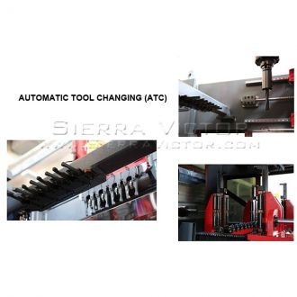
- AUTOMATIC TOOL CHANGING (ATC): Three automatic tool changing unit are provided, one for each spindle and each unit has four stations for different tools
- The ATC system enables the machine to change tools quickly and automatically, thus eleminating manual intervention and reducing downtime of the machine
- Capacity: 8kg for each station
- MATERIAL CLAMPING SYSTEM: Beams are clamped on the horizontal plane between rollers hydraulically and vertical clamping is performed hydraulically by pressure apparatuses. Deflections and vibrations generated during drilling operation are prevented thanks to 16 hardened rollers that come in contact with the beam from both sides
- MARKING: Marking with scribing tools on 3 surfaces of beams is provided.
- Scribing depth: 1-3mm
- Air motor speed: 19000 rpm / 6 bar
- HYDRAULIC MARKING UNIT: Hydraulic marking unit is provided as an option. Hydraulic marking can be performed only on an exterior surface of beams by hydraulic cylinder pressure. 40 characters including letters and numbers are available on the rotating disk, which is positioned through a servo motor
- Characters height: 15mm
- Characters depth: 1-3mm
- INFEED AND OUTFEED CONVEYORS: The heavy steel conveyors provide a steady structure for processing. The height of conveyors can be adjusted so as to keep the level the same
- The outfed steel conveyor rolls are motor driven
- Height: 800 mm (+/- 25 mm height adjustment)
- Max. speed: 15m/min
- TRANSFER TABLES: Transfer tables are integrated into the infeed and outfeed systems to ensure that the material is at the most suitable position for starting the operation and to remove the processed material from the working area safely besides eliminating the need for crane operations. The work-flow safety and continuity are also guaranteed with transfer tables
- BOTTOM SUPPORT UNIT: A bottom support unit is an optional feature provided on the machine to perevent deflections that occur on thin webs, plates, etc
- CHIP CONVEYOR: The chips that pile-up in the machine during drilling operations can be disposed with an optional chip conveyor.
- REMOTE CONTROL: The remote control allows the operator to check and inspect the process in safely without walking around
- SAFETY SWITCHES: If the doors are opened during production, the machine stops automatically to provide a safe working environment.
- SAFETY FENCING AND INTERLOCKING DOOR: A safety fence is provided upon request to prevent entering dangerous areas. The safety fence has various types and dimensions.
- The interlocking door is integrated with safety fencing. When the sensor notices that the interlocking door is opened, all systems of the relevant zone will be shut down immediately.
- LIGHT CURTAIN: Light curtains are provided upon request to detect approaches in a dangerous area. When a light curtain is crossed, all systems of the relevant area will be shut down immediately.
- CE AND INTERNATIONAL STANDARDS: All Akyapak Drill Lines are in compliance with CE regulations and meet the following international standards
- Related Directives and Annex: Machinery Directive 2006/42/EC/Annex VIII
- Related Standards:
- EN ISO 12100:2010
- EN 12717:2001+A1:2009
- EN 60204-1:2006/AC:2010
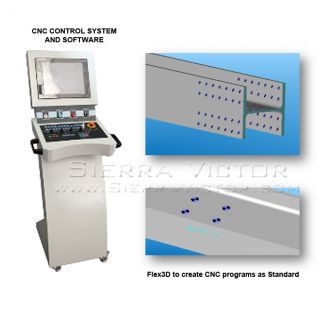
- CNC CONTROL SYSTEM AND SOFTWARE
- CNC CONTROL SYSTEM: Mitsubishi C70 Series CNC
- iQ Platform CNC CPUs: The Q173NCCPU enables CNC Control to be integrated with Sequence, Motion, and Robot automation systems. Also known as the C70 Series CNC Controller, an iQ CNC CPU system uses multi-purpose GOT1000 HMIs and on-rack I/O cards to minimize TCO on CNC line solutions
- Key Features:
- Accelerated communication speed over the inter-CPU shared memory
- Up to 16 axes with 4 simultaneously controlled axes per CPU, 2 CPUs per system
- 16.8k Block/min processing speed
- Streamlined production with reduced Tact Time and host information system linkage
- Uses GOT1000 HMI and iQ rack-based I/O card interfaces
- SSCNETIII benefits, including noise free, 50Mbps, fiber optic communication.
- Mitsubishi Touch Screen
- Programing Software: Lantek Flex3d SteelWork is a new module in the family of Lantek Flex3d products focused on designing and machining of standard profiles (I, U, L, T and square or round tubes).
- Lantek Flex3d SteelWork is a stand-alone product and it does not require any other additional Lantek software. Thanks to more than 20 years of experience in the sheet metal market, Lantek has been able to create a powerful off-line design and programming system for profile cutting machines in all their different versions: Sawing and drilling
- Easy and Flexible Design: Lantek Flex3d SteelWork allows for 3D design in an intuitive and simple way, giving a real vision of the result that the user will obtain when drilling and sawing the profile on the machine. The user can create any type of standard profile in a very flexible way. It is a parametric system allowing the user to change the values of any of the operations made previously, including the possibility of changing the initial parameters of each profile (enlarge, shorten, etc.). Once the design process is complete, the user can simulate in 3D the head movement of the machine displaying each machining operation that is processed along the tube or the profile (profiling, drilling, sawing). The user can also generate the NC file to send directly to the machine. Lantek Flex3d SteelWork, can be adapted to work with any profile or tube machine.
- Technical Characteristics: Lantek Flex3d SteelWork displays the exact profile and simulates in 3D each process, reducing to a minimum the possibility of errors.
- It offers the user the possibility to create standard sections (I, U, L, T, circular or square tube etc). This eliminates the need for the user to duplicate the entry of information to create a profile. It is only necessary to select one of the standard base sections and insert the length and material. The system is based on database technology, allowing for the complete management of the different profile products and remnants and gaining really quick access to them.
- DSTV, SAT, and CAM importer: Lantek Flex3d SteelWork can import data generated by 3rd party CAD systems used for designing structures such as DSTV, SAT, and CAM files (DSTV fie importing is a standard feature. Importing of all other files such as SAT and CAM are optional features)
- It allows the user to import different formats including machining operations and make any modification for production. The system converts the DSTV, SAT, and CAM files into the native format for Lantek Flex3d which allows the user to apply modifications in a natural and easy way.
- It also has the possibility to modify, add, and delete any machining operation required for the profile. Lantek Flex3d can easily interpret the various properties of each file such as material thickness, material type, and quantity if supported by the imported format
- Design Options: Apart from the basic operations of drilling, shearing, marking, and sawing, the system offers the possibility to create cutting operations from geometry imported from the Lantek 2D module and imported formats such as DXF. There are also dimensioning features to check the measurements of any geometry or machining operations of the profile
- Lantek Flex3d SteelWork offers the user the possibility to apply the following operations:
- Automatic and semi-automatic drilling operations along the profile (any flanges and/or web)
- Automatic and semi-automatic cutting operations (sawing).
- Automatic tools for text and contour marking operations.
- Copy machining. The user has the chance to make copies of any machining already made on the profile. Modifications on machining will be applied to any copy of the original
- Cutting Profiles Simulation: Lantek Flex3d SteelWork allows you to simulate each profile operation such as, drilling, cutting, and the work zone. Lantek Flex3d SteelWork will automatically generate the NC file for each machine from the machined contours on each profile. Lantek Flex3d SteelWork detects any potential collisions automatically and gives the user the tools to modify them manually. The system will automatically avoid collisions where possible. Where collisions occur, the system will display them on the screen during the simulation phase.
- The user can also make zoom, movements, rotations, and different axis positioning on the profile while viewing the simulation. The operator also can make drawings on Tekla and transfer it to Lantek Flex3d SteelWork
- ONLINE SUPPORT: Online support can be provided by Akyapak engineers via Teamviewer, connecting to the customer’s computer on which Lantek is installed. The engineers can monitor the machine and analyze the data online and in this way problems can be solved easily and quickly, maintaining the running of your machine
- Broadband internet connection is required for the machine connection. Ethernet line is provided by the customer to where the machine is installed
- Specifications
- Options/Accessories
- AST 1200-1500 Bandsaw
- Chip Conveyor
- Tool & Material Measurement
- Initial Drilling Pack
- Scribing Marking Unit
- Dot Marking Unit
- Lights Curtains
- Remote Control
- Online Connection HUB
- Additional Input Conveyor, [4mt (13ft)]
- Additional Output Conveyor, [4mt (13ft)]
- Automatic Loading System 40ft.
- Automatic Unloading System 40ft.
- Custom Freight
AKYAPAK CNC Beam Drilling Line 3ADM 1200
ITEM: CNC Beam Drilling Line
MANUFACTURER: AKYAPAK
MODEL: 3ADM 1200
Manufacturer:
AKYAPAK
Machine Type
Machine Category:
Beam Drilling Machines
Controller |
Mitsubishi |
Operating Range (mm) |
Min. 200 x 80 Max. 1200 x 500 |
Drilling Units |
3 |
Drill Diameter (mm) |
10 – 40 (Carbide and U-drill) 40 – 50 (U-drill only) |
Thread Tapping |
M12 – M24 |
Drill Holder |
BT40 |
Spindle Speed (rpm) |
50 – 3000 stepless |
Spindle Power |
22kW |
Spindle Torque |
280Nm |
Tool Changer |
3 x 4 |
Weight per linear meter (kg/m) |
600 |
Spindle positioning speed / returning speed |
5 m/min |
Machine Weight |
12,303 lbs. (13000kg) |
| CAPACITIES |
ANGLE |
minimum |
mm |
80 x 80 x 8 |
inch |
3.15” x 3.15” x 1/3" |
||
maximum |
mm |
250 x 250 x 28 |
|
inch |
9.84” x 9.84”x 1.1" |
||
U CHANNEL |
minimum |
mm |
80 x 45 x 6 |
inch |
3.15”x1.77”x 1/4” |
||
maximum |
mm |
400 x 110 x 14 |
|
inch |
15.74“ x 4.33“ x 0.55" |
||
HEA |
minimum |
mm |
96 x 100 x 5 |
inch |
3.77”x3.93”x0.19” |
||
maximum |
mm |
990 x 300 x 16,5 |
|
inch |
38.9”x11.8”x0.64” |
||
HEB |
minimum |
mm |
100 x 100 x 6 |
inch |
3.93“x3.93“x 1/4" |
||
maximum |
mm |
1000 x 300 x 19 |
|
inch |
39.3“x11.8“x0.74“ |
||
HEM |
minimum |
mm |
120 x 106 x 12 |
inch |
4.7“x4.1“0.47" |
||
maximum |
mm |
1008 x 302 x 21 |
|
inch |
39.6“x11.8“x0.82" |
||
H WELDED PROFILE |
maximum |
mm |
1250 x 500 x 50 |
inch |
49.2”x19.68”x2" |
||
IPE |
minimum |
mm |
80 x 46 x 3,6 |
inch |
3.14”x1.81”x0.14" |
||
maximum |
mm |
770 x 268 x 15,6 |
|
inch |
30.3”x10.5”x0.61” |
||
IPN |
minimum |
mm |
80 x 42 x 3,9 |
inch |
3.14”x1.65”x0.15” |
||
maximum |
mm |
550 x 200 x 19 |
|
inch |
21.6”x 7.87”x 0.74” |
Specifications are subject to change without notice.
NOTE: Data is provided by the manufacturer.
WARRANTY: 1 YEAR


